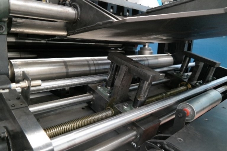
Coil Feeding Line
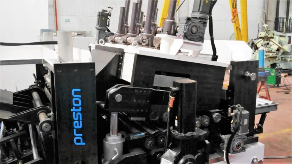
Roll Opening consists of sheet input to the straightener, roading groups, straightening and sliding groups.
The straightener consists of hydraulic inlet thrust rollers, lower and upper assemblies with back-up rollers, and driver roller pair.
The upper jaw group is opened hydraulically from the inlet side and provides convenience in the roll head inlet.
The drive servo motor consists of a driven pair of rollers.
Switch groups are optionally placed on the line.
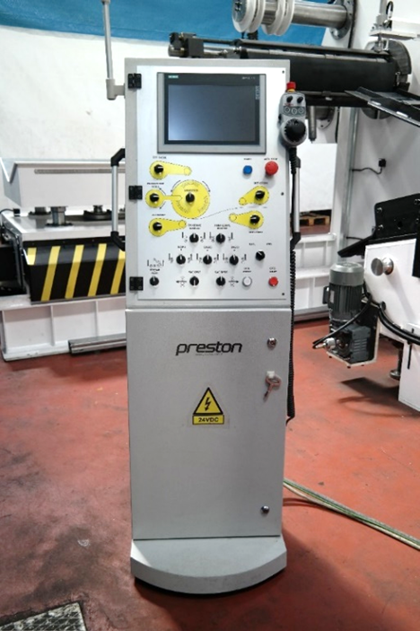
Control console
Control console with manual control button and 9” touch control panel and optionally handwheel can be added.
The manual buttons are:
1) Unrolling top press up and down rotary button
2) Unrolling rear support up and down rotary button
3) Chuck opening and closing buttons
4) Unroll and rewind rotary button
5) Lead in wings control buttons
6) Pinch roller control buttons
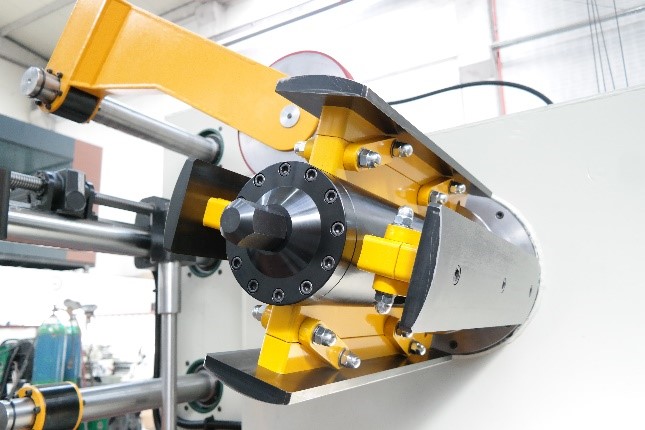
Chucks
Mirror opening and closing movement is performed with hydraulic cylinder. Scissor mechanism is used up to 5 tons of roll weight, then cam mechanism is used. Works between 480 and 540 mm as standard. Diameters can be changed according to customer demand. Designed and manufactured in such a way that the deflection at the end of the mirror does not exceed 3 mm when the coil is loaded and centered.
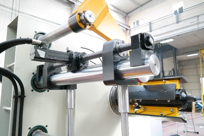
Servo Driven Coil Side Supports
The servo motor controlled coil side support arms are moved by a hydraulic cylinder, such as the upper thrust arm and the rear support arm, and aligned with the coil.
It approaches the coil from both sides by means of screw shafts operating in the opposite direction.
A "side support unit" is provided as standard in the opener. The latter is priced as an option if desired.
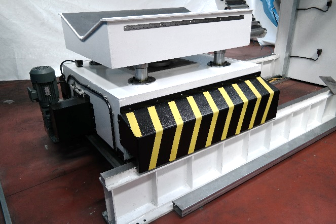
Coil Car
The movement of the roll trolley towards the opener is provided by an electric motor placed in the trolley. Rack and pinion gear is used for position accuracy. The electric motor is driven by an inverter. It slows down as it approaches the target and allows it to be positioned in the correct position.
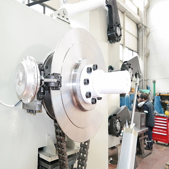
Caliper Disc Brake
Decoiler has a rotating disc mounted on the chuch.
The amount of sagging of the released sheet is continuously measured from the bottom. Decoiler speed and disc brakes are controlled by taking this precaution into account.
This ensures that there is always enough material in front of the feeder.
Control System
PLC & Motion Control : Siemens
• PLC: Siemens S7-1500 series
• HMI: Siemens KPT900
• Servo motor drivers: Siemens
• AC motor inverter: Sew, Siemens ABB or equivalent
Openable top
The upper group can be opened 20° or 30° depending on the machine size. This feature provides convenience in initial adjustment and maintenance.
The cylinders that move the assembly are hydraulic. If pilotage is desired, the same hydraulic cylinders are used for pilotage.
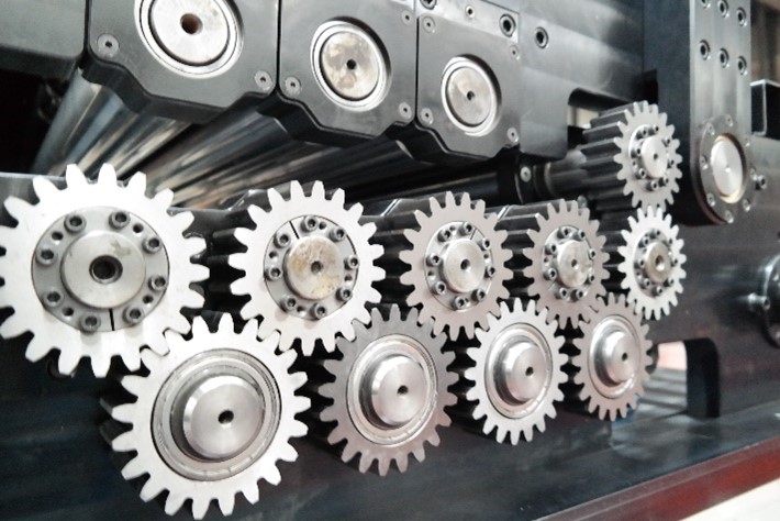
Gear system
To the extent that cylinder diameters and transferred moments allow, a direct gear transmission system is used. Otherwise, the movement is transferred by propeller shafts from a distributor gearbox to each cylinder.
The gears are manufactured from high-quality materials and profile grinding is applied to each gear.
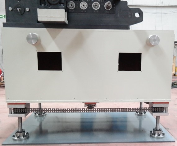
Height adjustment
The height adjustment comes as standard and is 200 mm. It is also driven by the servo motor as standard. 4 screw jacks are used.
Optional: Servo Driven Straightener Adjustment
The rectification setting is manual as standard. Optionally, the servo motor is added and becomes adjustable from the control panel.
Optional: Servo Driven Side Guides
The adjustment of the side guides in the straightener is manual as standard. Optionally, the servo motor is added and becomes adjustable from the control panel.
Optional: Handwheel
The handwheel and drive servo motor are controlled manually and precisely. Useful when the control panel is far from the mould and control is difficult in mould setting setups.
 English
 Türkçe

